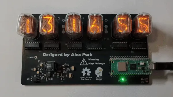
Nixie tubes are gas-discharge based displays that illuminate numbers by making metal numerals glow when a sufficient voltage is applied. They consist of a glass enclosure filled with a low pressure gas and metal digits inside. They were produced in countries all around the world in the 1950-70s, but the ones produced in the Soviet Union are the most popular today. Back in the day, these were used in places where digits needed to be displayed, such as in calculators, clocks, or measurement devices such as multimeters. Unfortunately, with few exceptions, these tubes are no longer produced today, but enthusiasts still adore them for their beauty. I discovered nixies a few years ago while watching youtube videos, but I never saw myself owning any. Recently, my interest in nixie tubes was rekindled when I learned my friend was making a project with them, and I was inspired to make a project of my own.
Choosing a tube
There are many types of nixie tubes, with varying sizes, styles, prices, and availability. Personally, I chose the ИН-12 (IN-12) tubes because they were available for cheap ($45 for 6), and they were reasonably big and readable. Most nixie tubes have their displays vertical, but the IN-12 is one of the few that are read horizontally.
170 Volts
When I was trying to find out what I needed to light up a nixie tube, I saw that I would need 170V DC. I looked online and found this power supply someone made on GitHub as a reference, and copied the schematic. Some of the parts were a bit outdated, so I had to switch them out, and I bought mostly everything on LCSC instead of Digikey to save costs. If you do decide to make your own nixie clock, I don’t really recommend making your own boost converter as for me, it was a hassle and a bit sketchy (buy one instead). However, I wanted to make my own boost converter because it’s a really good learning experience. Also, high voltages like these have the potential to cause potentially fatal injury if handled improperly, so be careful!
Displaying digits
Nixie tubes are actually remarkably simple. They have one anode (+ terminal), and a cathode (- terminal) for every digit. You always have the anode connected (with a current-limiting resistor), and you choose which cathode to connect to ground in order to light up that specific digit.
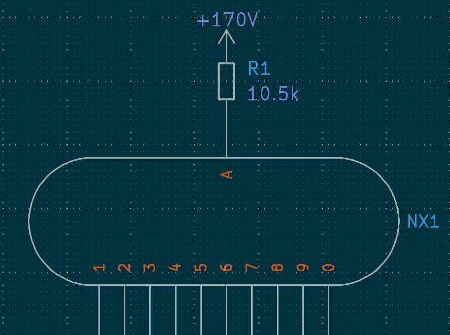
It’s really simple, except for the fact that switching 170V can be difficult, as most transistors or shift registers would be fried instantly. Out of the different ways you can switch the digits on and off, I decided to use the old K155ID1/SN74141 IC. It takes in 4 binary (electrical on/off) inputs, and lights up the digit that corresponds with the decimal equivalent. It works well and is simple, but the drawback is that they are somewhat expensive, and you have to buy them off eBay, and you’re using an 50~ year old IC. Other (more modern) nixie control circuitry include high voltage shift registers such as the HV5122/HV5222, or just using discrete transistors for each of the digits. More detailed info about nixie IC drivers can be found here.
The microcontroller
I chose to use the Raspberry Pi Pico W because of its inbuilt RTC (real time clock) and WiFi capabilities. It was also really cheap, available for just $6 and with plenty of GPIOs (I used 25). WiFi was a must-have for me because I planned to sync the time using NTP (network time protocol).
Designing a PCB
Using KiCad, I put together a schematic and then laid out and then routed all the components on the PCB. This was my second project I’ve done on KiCad, so I still was learning how to use the editor.
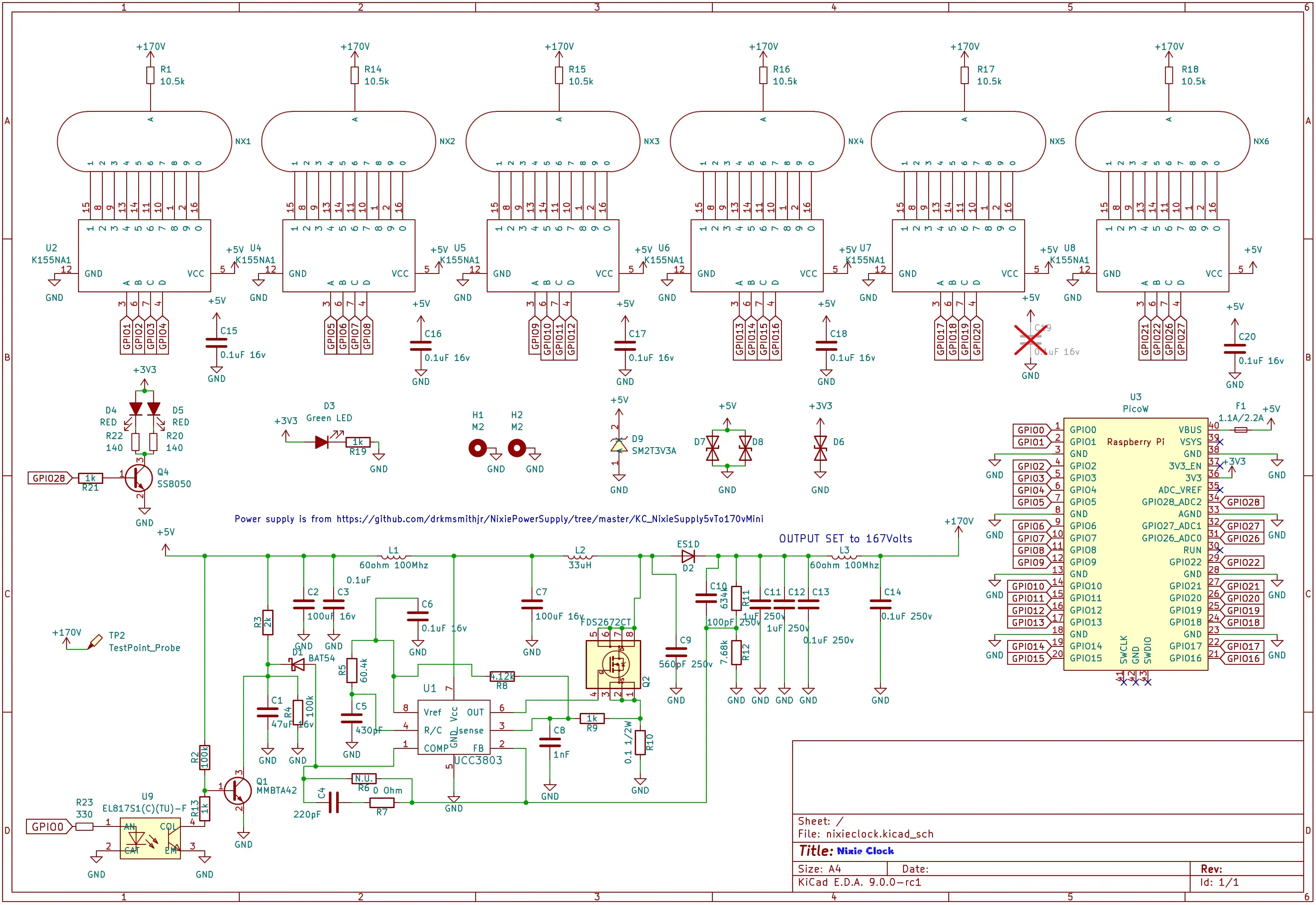
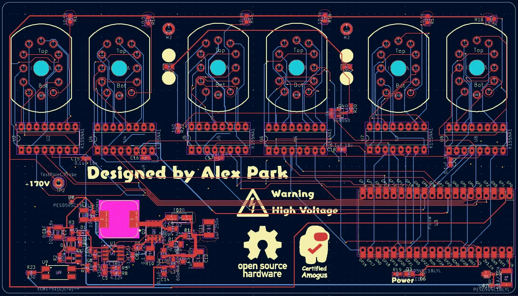
And yes, I know my routing is rather questionable, but I’ll get better at it over time.
I ordered the PCB and stencil from JLCPCB (they charged me a lot of large board fees), and the parts from LCSC and DigiKey (I had to buy an obscure inductor that was only on DigiKey).
Soldering SMD for the first time.
In past times, I just paid JLC to assemble all my SMD parts because it was convenient, and I didn’t know how to solder SMD. But this time, I had too many specialized parts that it would cost too much, and I figured I’d want to learn at one point. After consulting advice from a friend, I was told that using a hot plate would be the easiest method by far. While I messed up the first time because I failed to heat the board enough, the second time everything reflowed perfectly.
Success!
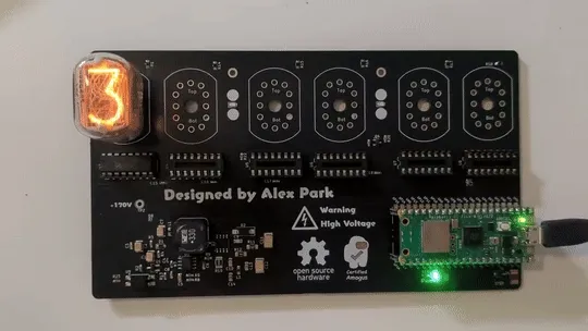
After assembling the board, I probed the high voltage output with my multimeter and was delighted to read about 167 volts. As a test, I plugged in one tube and cycled through the digits to make sure everything worked correctly, and sure it did.
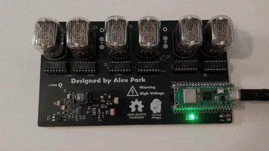
I soldered the rest of the tubes onto the board, and put the rest of the ICs into their sockets. After writing a bit of basic firmware and debugging things, the clock was complete! I also 3d printed a stand so I could keep it on my desk.
What happens next?
There are a few changes I would make in the second revision of this. Firstly, the boost converter is struggling with the current 5V input because of voltage drops due to resistance. Next time, I would probably add a 12V input as it would make the boost converter much more efficient and better at providing the needed voltage and current. I also made the spacing between the digits slightly too wide, and I would probably put them closer together in the next revision.
I really enjoyed making this project, and it’s a really cool and functional addition to my desk. Somehow I finished this in a month start to finish, designing everything during the week of final exams, waiting for things to ship over winter break, and assembling everything after the first week back at school. I would say this project took me about 20-25 hours in total, and cost about $150 excluding the cost of tools.
Nixie tubes are a hobby in itself, and I’ve barely scratched the surface with this project. Perhaps I might make more clocks in the future, who knows. Anyhow, I learned so much building this, and it was certainly a lot of fun. I know I’ve kinda neglected this blog recently, but hopefully I’ll post more things soon :)
And as always, all the design files and code for this project are open source at https://github.com/alx-alexpark/nixie-clock